The Guardline (GL) receiver (aka hub, aka RX) has only one NC/NO contact. You can assign all four zones to the NC/NO contact, but you will not be able to distinguish among the zones. That sucks. So…
Taking an idea from @specsix in the HA community forums, I wired the four LEDs in the GL RX, plus Ground, to GPIO pins on a Raspberry Pi. The Pi reads the high/low state of each led (approx. 2.6V) and my python code fires MQTT messages to communicate those events to Home Assistant.
Disassembly/opening the GL RX: Three small phillips screws are easy to find on the bottom. The 4th screw is behind a label. On the label is a cartoon of DIP switches 5,6,7,8. The screwhole is near “8 SELECT”.
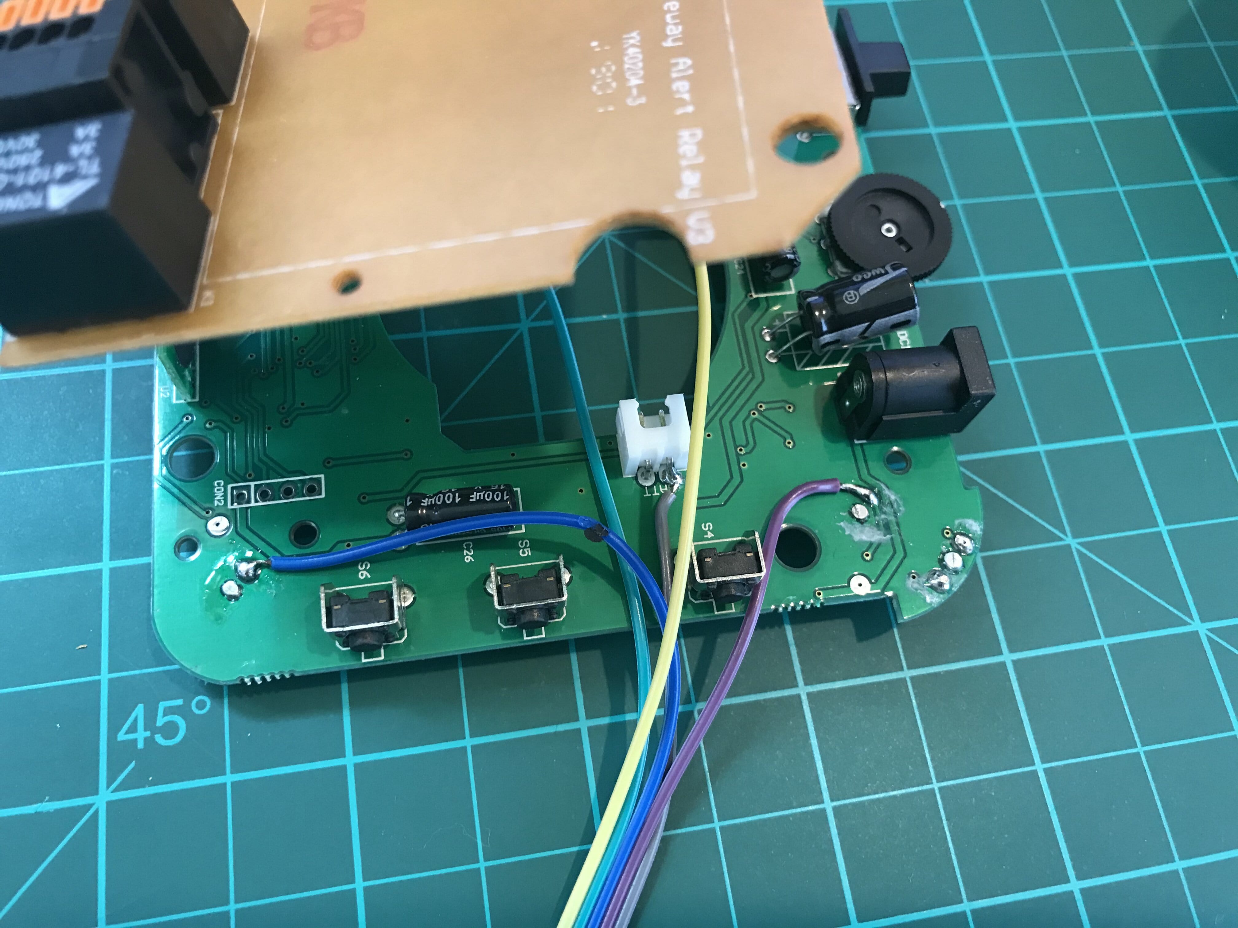
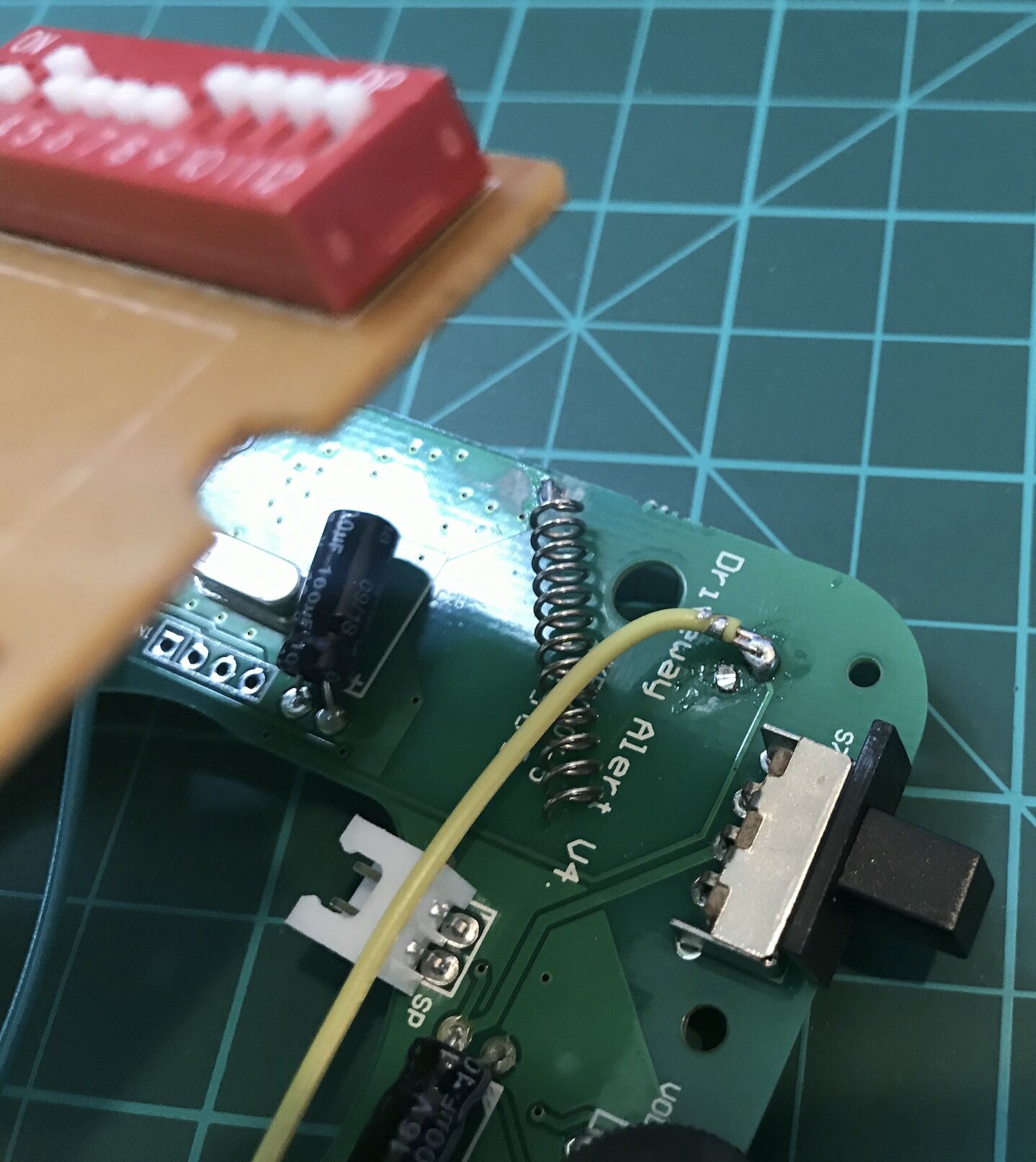
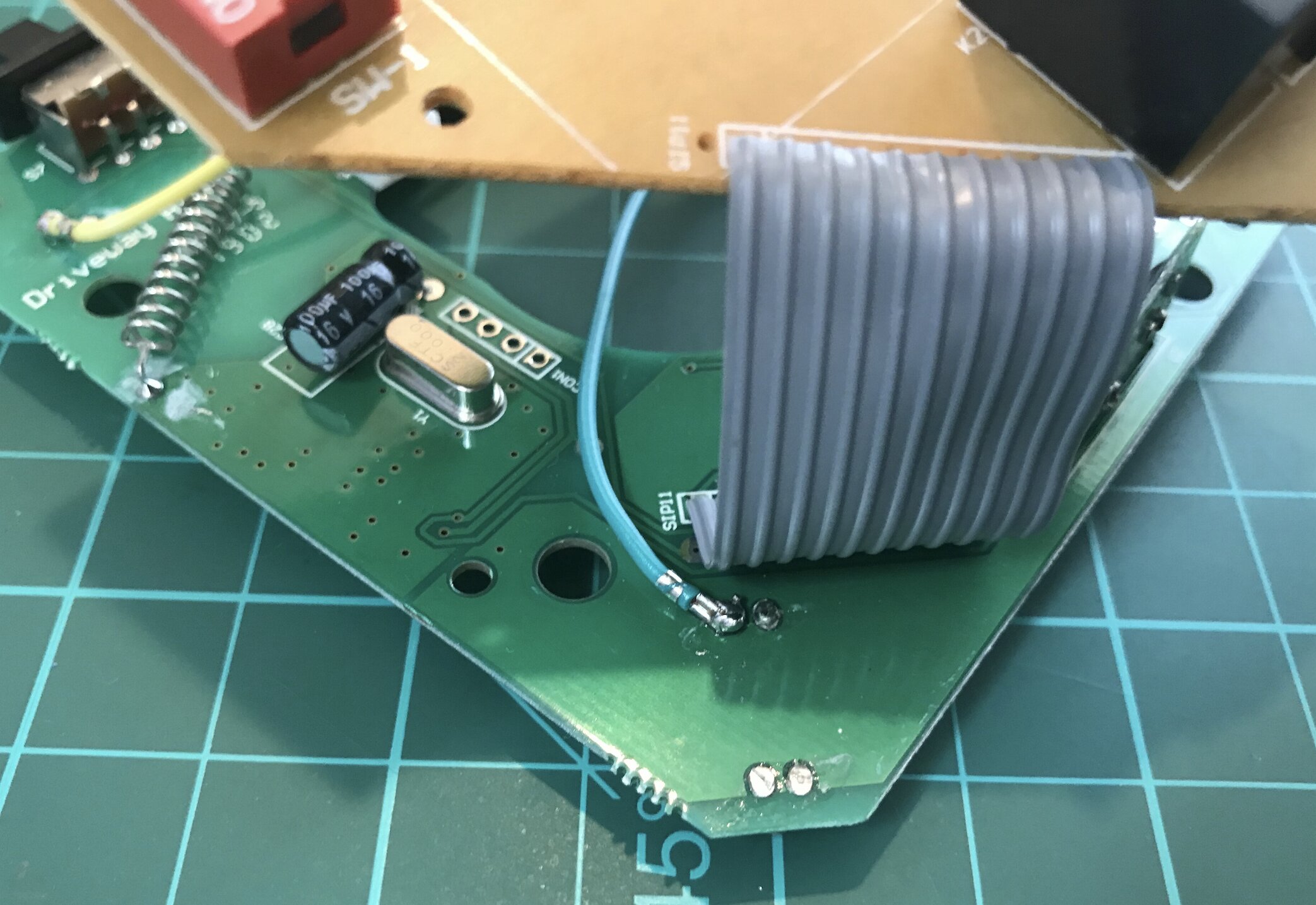
Here are the solder points for each of the four LEDs, plus Ground.
NOTE: this VOIDS your warranty and support, and you can end up with a destroyed GL RX.
NOTE: I have the 500-foot-range version. If you have the 1/4-mile version, your device will be completely different.
Above are the “hard” parts of the project, so I documented it first. Feel free to contact me or comment below if I should add more details.

Donn,
This is awesome! I have been racking my brain trying to figure out how to get this adequately integrated into Home Assistant.
Would you be willing to send me a sanitized version of your python script you leveraged for the gpio readings?
Thank you in advance for your time.